Acceptance test
Whether you bought a card or built one, check it before it goes near a machine you care about. The tests below go from cheapest to most revealing, and the last one — the bus loopback — is the one that actually proves the card.
This is hardware-level work, so it runs from the interactive menu application
(qbone-cli or unibone-cli) rather than the web interface. Start it and it
takes the board from the running service for the length of the session — see
Running the scripts you have
for what that costs and who is allowed to do it.
What you need
Section titled “What you need”Only +5 V. Connect it to the pins of the power capacitors or the +5V UB
pin header — not the BeagleBone’s own 5 V jack, which leaves part of the
circuit unpowered because the relay never closes.
For the bus tests the card must sit in an empty, terminated backplane. One terminator is enough and it must be passive: resistors only, no boot ROM.
1. Power
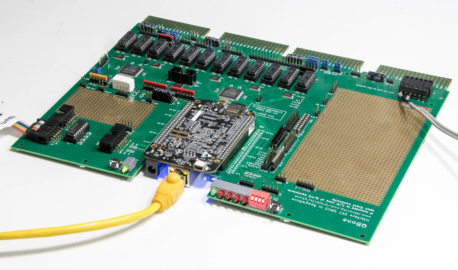
Section titled “1. Power”Apply +5 V. The power relay must switch after about a second’s delay; the BeagleBone then produces 3.3 V and the green LED comes on. That one-second delay exists to give the BeagleBone’s reset circuit a clean power-on ramp regardless of how oddly a vintage DEC supply comes up.
2. Boot and network
Section titled “2. Boot and network”The blue LEDs flicker while Debian boots. After 30–90 seconds QUniLator should answer on the network — see Find it on the network.
If it boots but never answers:
- Is the BeagleBone actually plugged into the card? (See the warning above.)
- Are the yellow and green Ethernet LEDs active?
- Try repowering. There is a long-standing bug in the BeagleBone’s Ethernet interface that occasionally prevents it coming up.
- Fall back to the serial console.
3. Serial ports
Section titled “3. Serial ports”The card exposes two RS-232 ports. UART1 is a Linux login; UART2 is available to the emulation — it is where the emulated DL11 serial card lands.
4. LEDs, switches and I²C
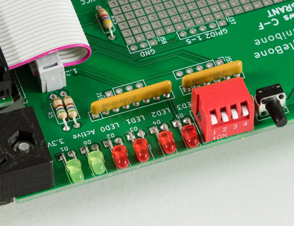
Section titled “4. LEDs, switches and I²C”The user LEDs and switches are ordinary GPIOs, not PRU-driven. In the menu application choose TG (GPIO) then LB (manual loopback): the four switches should drive the four LEDs. Pressing the button enables the DS8641 driver array, which lights the second green LED.
The card also carries a small I²C EEPROM holding the cape name, which is what tells the kernel which pin configuration to load. Reading it exercises the same I²C bus the add-on panels use:
hexdump -C /sys/bus/i2c/devices/i2c-2/2-0054/eeprom5. The bus loopback test
Section titled “5. The bus loopback test”This is the real test. Signals go out through the latch array and the DS8641 drivers onto the bus lines, and come back in through the drivers and input latches to the PRU pins. It exercises the card, the terminators, and a good part of the backplane.
Preparation:
- Card in an empty, terminated backplane.
- Fit the loopback jumpers on the grant lines.
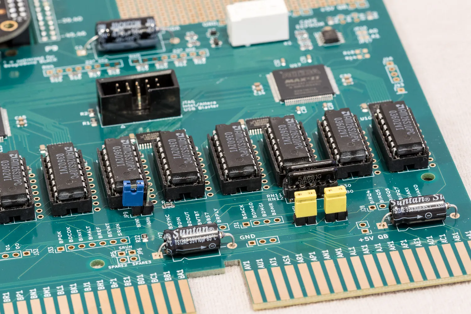
Run it: menu TL (test bus latches), then >>> * r to test every bus
signal endlessly with random patterns. Let it run as long as you can bear, and
stop it with ^C.
Reading a failure. The test prints the signal path for each failed bit.
Two things worth doing while it runs:
- Test the test. Pull one loopback jumper; the run should stop with an error.
- Bend and knock the card gently. That is what exposes a bad joint.
Remove the loopback jumpers when you are done.
6. A real device
Section titled “6. A real device”Then run it in a machine
Section titled “Then run it in a machine”If all of that passed, fit the card to a real machine and boot something — the configuration catalogue is the quickest route to a running system.